|
Carbide wear components could fail in a number of different ways. Unfortunately, there is no 'the best' grade of carbide for all wear applications. Replacing one grade with another may reduce the probability of one type of failure from occurring, but generally increases the chances that a different failure occurs. Carbide grades are normally selected so that the service life of the wear part and the type of failure are quite predictable. So unscheduled or disruptive outages of the assemblies which include the carbide component are avoided and the scheduled replacement of parts prior to failure is an option. Please find a brief description of each of the common types of failure as following. Abrasive Wear/Erosion Abrasive or erosion wear represents a form of mechanical attack at the working surface of the carbide component. It is the progressive loss of material at the carbide surface due to a high-velocity stream of liquid or gas containing solid particles directed into or flowing across the surface of the carbide. It may also result from the sliding or rubbing of a mating component or work material over the carbide surface. The rate of wear depends in part on the force or pressure with which the contact medium impinges on the carbide surface. The progressive wear caused by abrasion or erosion is a preferred mode of failure since it does not result in a total breakdown or stoppage of the operation depends on the failing component. Corrosion/Leaching Corrosion wear is the result of a chemical or electrochemical reaction between carbide surfaces and the environment. These reactions generally involve the metallic binder matrix (cobalt or nickel) rather than the tungsten carbide grains and, with the loss of the binder metal at exposed surfaces, the mechanical bond holding the carbide grains in place is also lost. Acidic liquids are particularly corrosive. A cobalt binder is far more susceptible to chemical attack or “leaching” than nickel and should be avoided in moderate to highly corrosive environments. Corrosion rate data for specific situations are seldom available and are typically determined empirically. Chipping/Fracturing Except at relatively high temperatures, carbides undergo little plastic deformation prior to failing by brittle fracture. Carbide grades vary widely in tensile strength and toughness and premature failure by chipping or fracture occurs whenever the carbide component lacks the toughness to withstand service conditions that include mechanical shock or impact. Sharp, unprotected edges are particularly vulnerable to chipping. Cracks generally initiate in areas associated with high-stress concentrations and, once moving, propagate rapidly through the carbide component to produce failure by fracture. Carbides have relatively high compressive strengths, however, and any change in either part geometry or operating conditions that convert tensile stresses to compressive stresses reduces the probability of failure by fracture. Design considerations that reduce the risk of failure by chipping or fracture include the use of protective edge chamfers and radii, avoiding sharp inside edges and other stress-inducing features, increasing the wall thickness of tubes and wear sleeves, and improving surface finishes. In certain instances chipping or fracture occurs as a result of the increased stresses associated with a badly worn carbide component. When this is the case, wear is the primary cause of failure even though catastrophic failure by fracture or breakage may mask it. Thermal Cracking Cemented carbides have relatively poor thermal shock resistance and sudden changes in temperature often produce failure by thermal cracking. Thermal cracks can result from thermal stresses developed in a single heating-cooling cycle if the temperature change is rapid and significant. These cracks often take the form of a network of fine cracks occurring throughout the bulk of the carbide component and normally result in catastrophic failure. Thermal cracks may also develop gradually over thousands of thermal cycles involving very small changes in temperature. The latter is more localized and typically occurs as closely-spaced, radial cracks that extend from edges of the part. As the process progresses these cracks deepen and widen resulting in the spalling away of the carbide located between them. Thermal Deformation Cemented carbides retain their hardness and strength to relatively high temperatures, but will deform plastically under load as service temperatures approach the softening point of the binder metal. Although deformation can occur with no loss of material at the carbide surface, even small changes in the size and shape of the carbide component may result in the failure of the assembly that contains it. Cratering Failure known as “cratering” is a localized form of erosion in which depression develops at the point where a continuous stream of metal or particulate-bearing liquid or gas strikes the working surface of the carbide component. At operating temperatures high enough to soften the binder metal (those exceeding about 900° C.) cratering can take place rapidly. Very fine-grained carbides are particularly susceptible to cratering since smaller grains are locked into the carbide surface by a relatively thin layer of binder metal. As the crater increases in size and depth, the carbide is weakened to the point where normal operating stresses produce mechanical failure in the area of the crater. Adhesion Wear/Galling Adhesion wear occurs when a carbide surface and that of a mating part or the work material rub together or slide past each other with sufficient force to create excessive friction and pressure at high points of contact between the materials. The high temperatures and pressures generated in these contact zones result in plastic deformation at the material surfaces, penetration of one surface by the high points on the other, and finally the transfer of material (welding) of one material to the other. As material builds upon one of the surfaces, the still higher points of contact create more heat, leading to more deformation, penetration, and material transfer. This process is often referred to as “galling”. Failure by adhesion wear can take several forms, but typically the buildup reaches a stage where it eventually is dislodged pulling chunks of the carbide surface with it. Carbide wear parts include carbide punch, die punch, carbide ejector pin, and punches and dies. The useful life of the carbide wear part is determined by many factors. These include the composition and properties of the carbide, the geometry of the carbide component, the design of the assembly, and the chemical, physical, and mechanical environments in which the carbide operates. Changes in any of these factors can produce an associated increase or decrease in service life. The chart below considers only one of these elements – the carbide grade. 
0 Comments
A cemented carbide is a composite material comprised of individual tungsten carbide grains imbedded in a ductile metal binder matrix of either cobalt or nickel. The physical and metallurgical properties of a particular ‘grade’ of carbide are determined by its composition (its constituents and their relative amounts), the size distribution of the tungsten carbide grains after sintering, the binder metal type and content, the quality of the raw materials used, and the workmanship with which the material is made. Those most commonly measured to assess the quality and define application areas are described below. The ASTM and/or ISO standard that applies to each of these measurements is also noted. Density or specific gravity is the weight per unit volume of a cemented carbide measured in grams per cubic centimeter (g/cm3). It is essentially the weighted average of the densities of all of the components contained in the product and is therefore a check on its composition. For grades containing only tungsten carbide and a binder metal, the density of the composite decreases as the lighter binder metal content increases. Hardness is the resistance of a cemented carbide to penetration by a diamond indenter under a specific load. It is measured on the Rockwell A (Ra) scale in the US and on the Vickers (HV10 or HV30) scale in Europe and elsewhere. Hardness is primarily a function of composition and grain size with higher binder metal contents and coarser tungsten carbide grain sizes producing lower hardness values. Conversely, low binder contents, and fine grain sizes produce high hardness values. Hardness is directly related to abrasive wear resistance. Transverse Rupture Strength (TRS) is a measure of the tensile strength of a cemented carbide in a three-point bending test performed on standard rectangular bars. It is reported in units of pounds or thousands of pounds per square inch (psi or kpsi), or in Newtons per square millimeter (N/mm2). TRS is perhaps the best measure of the relative utility of individual production batches since it surveys a reasonable volume of material and will detect low levels of critical internal defects. Products having relatively high TRS values are generally applied where shock, impact, or failure by breakage are factors. Residual Porosity is determined by visually examining the polished surface of a sintered sample at 100X or 200X magnification. Ratings for “A” type porosity (pores less than 10 microns in diameter), “B” type porosity (pores larger than 10 microns in diameter), and “C” type porosity (carbon inclusions) are determined by comparing the size and frequencies of each pore type in the sample with those in standard photographs. Each standard photograph is associated with a numerical rating that is used to represent the porosity levels in the sample. In general, edge strength and toughness decrease as the level of residual porosity increases. At high levels of porosity, the wear resistance of the product may also be adversely affected. Magnetic Saturation is the degree to which the metal binder in a cemented carbide is saturated with carbon. It is most useful for materials having a cobalt binder. For a known cobalt content magnetic saturation values indicate how much carbon the cemented carbide contains – from unacceptably low values that indicate the presence of an undesirable carbon-deficient phase (known as eta phase) to unacceptably high values indicating the presence of free carbon (carbon “porosity”) in the product. Magnetic saturation is sometimes used as an indicator of relative strength among lots of a specific grade. Coercive Force is the strength of the magnetic field required to demagnetize a fully magnetized cemented carbide sample. Coercive force is typically measured in oersteds (Oe). The coercive force measurement depends on many factors including composition, sintered grain size distribution, residual porosity levels, and others. It is sometimes used as an alternative indication of hardness but is best interpreted in combination with other properties as a measure of overall grade uniformity. Below we can see an example grade chart from CB-Ceratizit, from which JLS Precision Mold Part LTD mainly purchased the carbide rods. Their products are used to produce wear components including carbide punch, and punches and dies, die buttons, ejector pin, etc. 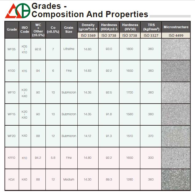  There are 5 factors that can increase punches and dies tool life and profitability, ensuring fabricators get the most out of their die punch tools, avoid tool wear, and punch proper shapes.
To get the most out of your punching tools, reduce tool wear, and punch proper shapes, take a look at the following five factors. 1.Correct Alignment One of the biggest mistakes fabricators make is not ensuring their turret stations are properly aligned and in good working order, not only positionally but angularly towards what is being punched. If the station is in good alignment but is turned by half a degree, nibbling or punching out a straight line, say with a rectangular tool, will cause a saw-tooth effect with every hit made. As time passes, this saw-tooth effect will result in uneven wear on the tool, breaking down the cutting edge. Nibbling creates side loading, where the punch starts to come down and only a portion of the tool hits the material. Most of the tool is left unsupported, which causes the tool to pull to the unsupported side, causing a breakdown of the punch point. If you are going to nibble, experts recommend using a fully guided tool with a stripper designed with a tighter clearance to keep the punch point vertical when penetrating through the sheet. This is especially good for small holes in thick material or nibbling. 2.Treatments and Coatings Coatings and treatments are a great way to extend punch life and decrease galling. The coating is one of the easiest ways to get the most out of your punching tools. Several different tool treatments and coatings are available, such as a nitride treatment in which nitride is infused into the punch point. That helps with making the die punch more slippery as it is punching through and pulling out of the material. Coatings such as zirconium, titanium, and nitride are applied in multiple, thin layers onto the punch point. That adds lubricity and helps keep the punch point cooler for high-hit applications that are subject to heat buildup on the punch. 3.Proper Die Clearance The right clearance is critical, It has a huge bearing on the stress factor on the tooling, and not to mention the finish on the hole itself. If you are aware of the appearance of burr, this is a good indicator that the die clearance is incorrect. Too much die clearance will cause the material to roll over and stretch, creating a downward edge or burr. If the clearance is too tight, this can result in extreme stress on the tool, with the punch stripping out of the pierced hole. When you have proper die clearance, you get better stripping, and a smaller burr and die clearance is material-dependent. With stainless, fabricators would typically adjust the die clearance to 25 percent of the material thickness. With mild steel and some types of aluminum, the die clearance is less than stainless, about 20 percent, depending on what is being punched out. 4.Sharp Tools Having a sharp tool can make all the difference in punching hole quality. The easiest way to know when your tool needs to be sharpened is by feeling it. If it’s dull, then it needs sharpening. you can also tell by the quality of the hole if there is a rollover on the edge of the punch, which could be an indication of a dull tool. A distorted hole also can show signs of the punch breaking down. For example, a round hole that starts looking egg-shaped could indicate that one side of the tool is breaking down before the other. You can hear the difference when the punch is hitting a sheet when it is starting to get dull, it is recommended that fabricators sharpen their tools more frequently rather than punching away until they are extremely dull. It’s better to sharpen more often and take minimal material off each time. This will drastically increase the tool life. For example, in side-by-side testing of the same tools in the same application, sharpening more frequently can improve tool life exponentially. For sharpening, using good coolant is essential. If you sharpen without coolant, the heat buildup can change the characteristics of the material, weakening the tool. And use a good grinding wheel and consistent speeds to feed the tool in and out. Once you’ve finished sharpening, it is essential that you demagnetize your tools. When they become magnetized, they attract any carbon-type debris. Any extra dust or debris on the tool increases the amount of wear. You are essentially punching through extra garbage. After tool sharpening, you may see a burr at the edge of the punch point. To get rid of this, use a soft abrasive stone to break off the material. It will leave a clean edge with a minimal radius. With dies, after sharpening, use die shims to make sure they are set back to the right height to ensure you have the right punch penetration all the way across the board. 5. Lubrication Some fabricators will run their punches without lubrication, which can reduce the life of the tool by up to 60% and cause galling when working on softer materials. Properly lubricated punch tips also will keep the punch from overheating. Besides these five factors, make sure you have a proper storage system for your punch and die to ensure they are not rolling around and getting scratched.  Tungsten was discovered by Juan José and Fausto Elhuyar, Spanish chemists and brothers, in 1783 in samples of the mineral wolframite ((Fe, Mn)WO4). Today, tungsten is primarily obtained from wolframite and scheelite (CaWO4) using the same basic method developed by José and Elhuyar.
Tungsten carbide is extremely hard. With a Vickers number of around 2600, it is about as hard as ruby and sapphire. So it can only be polished and finished with abrasives of superior hardness such as cubic boron nitride and diamond powder, wheels, and compounds. With Young's modulus of approximately 530–700 GPa (77,000 to 102,000 psi), it is about twice as strong as steel. It will buckle when a shear force of 274 GPa (shear modulus) is applied. Other properties are:
 What is Die/Mould?
A die is a specialized tool used in manufacturing industries to cut or shape material mostly using a press. Like molds, dies are generally customized to the item they are used to create. Products made with dies range from simple paper clips to complex pieces used in advanced technology. Die Forming Forming dies are typically made by tool and die makers and put into production after mounting into a press. The die is a metal block that is used for forming materials like sheet metal and plastic. For the vacuum forming of plastic sheet only a single form is used, typically to form transparent plastic containers (called blister packs) for merchandise. Vacuum forming is considered a simple molding thermoforming process but uses the same principles as die forming. For the forming of sheet metal, such as automobile body parts, two parts may be used: one, called the punch, performs the stretching, bending, and/or blanking operation, while another part that is called the die block securely clamps the workpiece and provides similar stretching, bending, and/or blanking operation. The workpiece may pass through several stages using different tools or operations to obtain the final form. In the case of an automotive component, there will usually be a shearing operation after the main forming is done and then additional crimping or rolling operations to ensure that all sharp edges are hidden and to add rigidity to the panel. Mold Components The main components for die toolsets are: Die block – This is the main part that all the other parts are attached to. Punch plate – This part holds and supports the different punches in place. Blank punch – This part along with the blank die produces the blanked part. Pierce punch – Also called die punch, along with the pierce die removes parts from the blanked finished part. Stripper plate – This is used to hold the material down on the blank/pierce die and strip the material of the punches. Pilot – This will help to place the sheet accurately for the next stage of operation. Guide, back gauge, or finger stop – These parts are all used to make sure that the material being worked on always goes in the same position, within the die, as the last one. Setting (stop) block – This part is used to control the depth that the punch goes into the die. Blanking dies – See blanking punch Pierce die – See pierce punch. Shank – used to hold in the presses. it should be aligned and situated at the center of gravity of the plate. Dongguan JLS Precision Mold Parts Co., Ltd is highly capable of manufacturing carbide punch and die, die buttons, die bushings, punches and dies, JLS wear components are widely serving for metal stamping, metal fabrication, injection mold industry, plastic mold/die makers, metal mold/die makers, tool and die maker, tool design& die making industries.  Carbide material is extremely hard by their inherent nature. The most typical carbides used in the tooling industry are Tungsten Carbide, Titanium carbide, and tantalum Carbide. They are formed from powders into sintered forms with different shapes as required.
Tungsten carbide is more and more commonly used in the tooling industry, it can be ground to various shapes such as carbide punch, punch and die, and die punches and buttons used as mold components in the metal stamping process. Sintering is processed in a high temperature where particles are compacted and under high pressure and temperature, the particles begin to fuse together and form a solid (although porosity with some small pores between the particles). So sintered carbides are actually very brittle and susceptible to break on sudden shocks which are prone to happen in machining if the tool encounters a hard inclusion or a sudden change in temperature during the process. In cemented carbides, a metal binder material is added to the carbide particles during the sintering process which gets into the gaps between the fused carbide particles and acts as a binder and cements the particles together. They act as a toughener due to the metals inherent ductility, offering improved tool life in machining. The metal used is most commonly Cobalt (Co). Cemented carbides are therefore carbides cemented in a metal.  Various tests have been devised to evaluate the wear characteristics of hard materials. One of these, ASTM G65, tests dry abrasion resistance- silica sand is rubbed against the specimen by a rubber wheel. The abrasive action highlights another source of wear for carbides; it tests the strength with which the binder holds the hard tungsten carbide particles in place. When these wear-resisting particles are torn loose from the binder, the rate of wear is increased. (Ceramic materials, being monolithic in structure, do not have this characteristic weakness.) Many applications require that these forces be resisted, therefore carbide grades have been developed to increase cement strength.
One carbide manufacturer makes a grade which increases cement strength by reducing the binder content to 3% cobalt, the carbide grain size to less than one micron, and incorporates a tantalum carbide additive; it has a measured hardness of 2250 kg/mm2 and resists abrasive wear 5 times better than his standard wear grade (6% cobalt, the hardness of 1700 kg/mm2). Another manufacturer, employing a different binder, chromium cobalt, makes a grade with a measured hardness comparable to his standard grade, but dry wheel abrasive wear is improved by a factor of 5. By varying the content of carbides in this way, materials are created with the characteristics to meet an extensive range of wear applications having different requirements. In addition to hardness and abrasive resistance, other characteristics may be important and can narrow the scope of the search for materials of choice. Density, electrical thermal conductivity, transverse rupture strength (beam strength(, impact resistance, hardness at elevated and reduced temperatures, modulus of elasticity, modulus of rigidity, compressive strength, corrosion resistance (acids, alkalis, and water), coefficient of friction, coefficient of thermal expansion, and magnetism are most of them.  When you are designing a wear part, such as punch and die, and die punch, which material would you choose?
The first carbide for a wear-resistant part application was invented in Germany in 1913. It was produced from two carbides, tungsten, and molybdenum, and the part was an insert for wire drawing die. From that early start, many different cemented carbide materials evolved having a wide range of properties to resolve wear-part problems. This period also saw the first engineering ceramics materials for wear-resistant applications, and they are now a large and rapidly growing market segment. Today the array of available materials is very large, and designers are finding it difficult to choose the best wear part materials for Ticn coated punch, metal stamping, tooling, and product component applications. Material characteristic information is published by the manufacturers of both carbide and ceramics materials, but often the information is aimed more at selling the product in providing engineering guidance. Some published information on ceramics, for example, presents hardness as the determining factor for resistance to wear. It then compares the measured hardness of the ceramic material with that of carbide and draws the conclusion that the higher hardness of ceramic material means superior wear resistance. This is an improper and erroneous conclusion. Hardness is a primary characteristic of wear-part materials, but it is a slippery property to define when comparing non-related materials (i.e. ceramics to carbides) for a range of different applications. This becomes evident with this question: Why does an EDM wire guide or a drill bushing of cemented tungsten carbide, with a measured Vickers hardness of 1700kg/mm2 (92 Rockwell A), have a useful life substantially greater than one made from a ceramic whose hardness is measured at 2100 (94 Rockwell A)? The reason for this apparent departure from the norm is basic, easily grasped, and the design engineer needs to understand it in order to work knowledgeably with hard materials.  What is Tungsten Carbide?
Tungsten Carbide begins as a distributed mixture of tungsten carbide powder (WC) and a small amount of binder powder, which is generally cobalt (Co). The mixture is processed, shaped, and sintered. The sintering process liquefies the binder, which when cooled, forms a cement. The hard tungsten carbide powder grains are rigidly embedded in the cement. There are several different grain sizes for carbide - submicron, fine, medium, coarse, and extra course. The percentage of binder in the carbide has a direct effect on the properties of the finished product. A 3% cobalt binder with a fine grain size has the best wear resistance but is extremely brittle. The Rockwell C for this formula is 80 – 82 with a Transverse Rupture PSI of 225,000 and a Compressive Strength PSI of 660,000. This grade is used for sandblasting nozzles, spray nozzles, drawing dies for soft metals, and for wear protection in linings. A 22% cobalt binder with extra coarse grain size is extremely impact resistant and break resistant but is not as resistant to wear as a lower percentage, finer grain grade. The Rockwell C for this mixture is 60 – 62 with a Transverse Rupture PSI of 350,000 and a Compressive Strength PSI of 480,000. This grade is used in cold and hot forming tools, pressing dies, drawing tools, for fabricating rods, valves and springs, hammer jaws, and shredders for scrap processing. One of the grades that we commonly use is made up of a 6% cobalt binder with fine grain size. This grade works well for wear protection and machining, milling, drilling, and lathing of aluminum, copper, silver, gold, graphite, and glass-fiber-reinforced plastics (GFP). The Rockwell C for this formula is 79 – 81 with a Transverse Rupture PSI of 275,000 and a Compressive Strength PSI of 700,000. Carbide is used to produce gages, plungers, bushings, dies, pins, and mandrels. Another binding agent commonly used with tungsten carbide is nickel. Nickel grade carbides are extremely corrosion resistant and are generally not attacked by acids, bases, wastewater, or organic solutions and can be formulated to be non-magnetizable. The Rockwell C for a formula containing 6% nickel with fine grain size is 78 – 80 with a Transverse Rupture PSI of 275,000 and a Compressive Strength PSI of 690,000. The nickel grade carbide is utilized to make plungers and bushings for pump construction, seals, guides, mixing rods, slide rings, spray nozzles, cutting blades, grinding and mixing systems, and in plastics processing. We can work with you to determine the correct grade with the right mix of wear and impact resistance for your application. Dongguan JLS Precision Mold Parts Ltd. imports tungsten carbide from USA, Taiwan, Europe, ensuring the correct hardness, corrosion resistance, making the best punches and bushings die punch, precision carbide punch, carbide ejector pin. Flawless surfaces before shipment. |
AuthorAbby Zhang Archives
August 2021
Categories |

 RSS Feed
